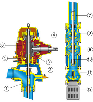
D series with MR control
D series with MR control – Tractor / Diesel engine
Vertical axis pumps for bored wells D MR
6 “, 8”, 10 “well pumps and electric pumps
SECTION
1. Delivery base
2. Driving shaft
3. Bevel gear pair
4. Power takeoff shaft
5. Cooling coil
6. Lubrication circuit
7. Line shaft
8. Body pump
9. Impeller
10. Pump shaft
11. Foot valve
12. Strainer
VERTICAL AXIS CENTRIFUGAL PUMPS
“D” Serie
CONTROL UNITS - "MRE" and "MR" SERIES
For particular applications, such as in fire-fighting systems, special versions are supplied on request: as an alternative they can be driven by more motive powers such as thermic motor., electric motor or tractor (series MRE). The execution on the same end of a cylindrical double shaft protrusion, with feather and spine, allow a mixed driving of the right angle gears through the thermic motor or the tractor (series MR).
THE PUMPS
Made up of a series of modular stages, they are provided with a fi tting for the upper pipe and normally with a foot valve flanged to a suction rose in galvanized steel which prevents the foreign matter from getting into the suction system. The pump bodies and the valve body are made in fine- grained gray iron, the impellers with semiaxial flow and dynamically balanced, are available in cast iron or in bronze on reques.; the pump shaft guided by wearproof rubber bearings, is in hard-chromed carbon steel or in stainless steel on request.
THE LINE SHAFT
It is formed by a rising steel pipe with double flanged trunks whose standard length is 3 Mt. It makes it possible for the pump to be positioned in depth and to convey water. Driving is performed by rods guided on each end by wearproof rubber bearings which keep a perfect alignment of the driving axle in all installation depth. Near each rubber bearing, the rods are protected by hard-chromed wear brass bushes. The threaded connection sleeves and the rods are made in carbon steel or in stainless steel on request. The rubber bearings are arranged in the middle of a cast iron support placed between the pipe flanges.
USES
Deep water lifting. Installation in boreholes or in the open. Irrigation systems, water systems, industrial and fire-fighting systems.
USE LIMITS
Mechanically and chemically non-aggressive fresh water lifting according to the materials normally used in production.
Max. water temperature: 40° C.
Maximum water hardness: 40 g / m³.
Installation depth: up to 120 mt., in standard execution.


